









Foreword
Thank you for choosing our products!
To enable you to have an overall understanding of our company, there is a detailed introduction regarding features, structural features, technical parameters, instructions for use and maintenance of the product in the Manual. Before using this product, please read this Manual carefully, which will help you to use it better.
Due to constant update of product functions, the product you received may differ from the description in the Manual. We hereby express our deep sorry for this matter! During use, in case of any question, please timely call us for consultation, and we will offer dedicated service to you wholeheartedly.
1.1 Product Parameter
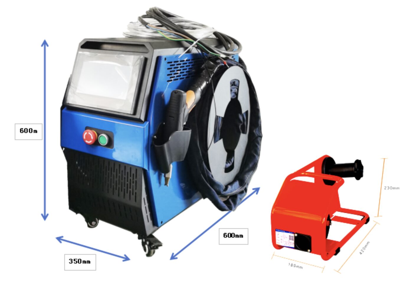
Spot Laser Welding Machine
Nome | Intelligent dual-pendulum handheld welding head | |||
|---|---|---|---|---|
Modello | FWH30-DS10E-V4-T | |||
Fiber interface | QBH | |||
Wavelength scope | 1,070±20nm | |||
Potenza nominale | ≦3,000W | |||
Lunghezza focale di collimazione | 40 mm | |||
Focus focal length | 150mm | |||
Swing type | — 、 ○ 、 ∞ 、Z 、 ◎ 、 △、m | |||
Regulating scope of focal point | - 10mm~+10mm | |||
Regulating scope of light spot | 0~5mm | |||
Auxiliary pressure | ≤1Mpa | |||
Scanning range | φ20mm | L20mm*W5mm | L20mm | φ20mm |
Scanning type | ○ |  | —— |  |
Scanning range | L20mm*W5mm | L40mm*W40mm | φ20mm | L19mm*W20mm |
Scanning type |  | + |  |  |
Cellula | 1.0Kg | |||
1.2 Precautions
※ To ensure personal safety, wear the special fiber laser protective glasses before operation.
※ It is necessary to keep the product clean and prevent the cooling liquid, condensate water or other foreign matter from intruding into the cavity, or the functional contamination and functional impact of related parts will be incurred.
2.1 Product structure

3.1 Pipe connection
Cooling water circuit and auxiliary protective gas connection

Connection of cooling water and shielding gas and usage requirements:
Note: Regularly used gases: Compressed air (oil-water filtration required)
Regularly used gases are: argon, nitrogen and compressed air (oil-water filtration required).
3.1.1 Cooling water
The 6mm air tube is connected. The main function is that the excess heat is taken away by cooling through the internal
structural member water route when the heat is produced by the light path in the cavity to ensure the welding performance. The series connection of cooling water pipeline is required, with one-in and one-out water circulation connected.
3.1.2 Protective gas
The 6mm air tube is connected for butt welding gas protection, with input pressure<1Mpa.
3.2 Optical fiber input installation
※ The QBH is a horizontal arrangement to take out the dust proof seal cover.

※ Align the red dot on the fiber optic head with the QBH red dot, and slowly insert the fiber optic head into the QBH.
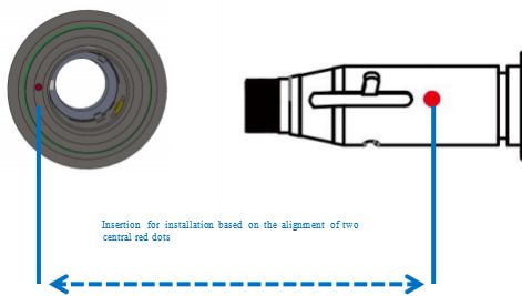
※ The QBH is screwed to the locking state: Rotate it to the
limiting position clockwise (hearing the "click"), lift up the rotating mantle, and clockwise rotate the mantle until the head of optical fiber is compressed.

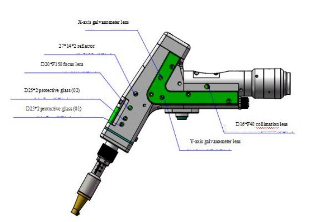
4.1 Structure of optics lens
※ The assembly is completed in the dust-free plant at the time of replacement of parts. In principle, other modules are forbidden to be dismounted except that the protective glass drawer can be disassembled and assembled. If it is necessary to check the collimating lens, focus lens and galvanometer lens, the product shall be put into a clean environment for disassembly.
4.2 Cleaning of optics lens
※ When the optics lens are cleaned, the operation method and attention points are as follows:
※ Tools: Dust-free gloves or dust-free fingerstall, dust-free wiping cotton swab, isopropyl alcohol, and caned dry and pure compressed air.
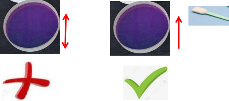
※ Spray the isopropyl alcohol onto the dust-free cotton swab, align the lens to eyes, gently pinch the side edge ofthe lens with left thumb and index finger and hold the dust-free cotton swab with right hand to gently wipe the front and back ofthe lens in a single direction from bottom to top or from left to right (avoid wiping back and forth to avert the secondary contamination of lens), blow the surface ofthe lens with filling dry and pure compressed air and confirm the surface of lens is free from foreign matters after cleaning.
4.3 Disassembly and assembly of optics lens
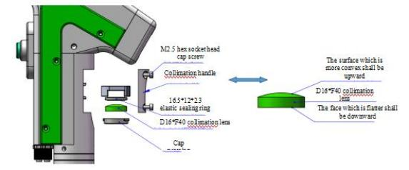
4.3.1 Disassembly and assembly of collimation lens
Tools: 2mm inner-hexagon wrench, dust-free cotton swab, alcohol
※ The disassembly and assembly shall be completed in a clean place. When the lens are dismounted, the dust-free gloves or dust-free fingerstall.
※ Disassembly and assembly steps:
Step 1: Clean up all the dust on the surface of the laser head firstly.
Step 2: Loosen the M2.5 hex socket head cap screw in the figure by hand with a 2mm hex wrench.
Step 3: Remove the collimation handle horizontally, and pull out the collimation drawer module.
Step 4: Seal the port with textured paper to prevent the dust from entering the cavity, resulting in pollution.
Step 5: Rotate the gland for 90° after pressing it downward gently and take out the gland by two bosses aligning to left/right opening to replace the collimation lens.
(Note: orientation of installed lens in the concave and convex direction)
4.3.2 Disassembly and assembly of focus lens
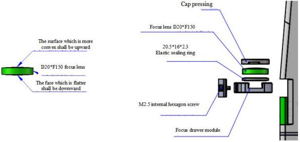
Tools: 2mm hexagon key wrench, dust-free cotton swab, ethyl alcohol and masking tape
※ The disassembly and assembly shall be completed in a clean place. When the lens are dismounted, the dust-free gloves or dust-free fingerstall.
※ Disassembly and assembly steps:
Step 1: Loosen the M2.5 hex socket head cap screw in the figure by hand with a 2mm hex wrench.
Step 2: Take out the focus drawer module by direct drawing/pulling in the horizontal direction.
Step 3: Seal the port with textured paper to prevent the dust from entering the cavity, resulting in pollution.
Step 4: Rotate the gland for 90° after pressing it downward gently and take out the gland by two bosses aligning to left/right opening to replace the focus lens.
(Note: orientation of installed lens in the concave and convex direction)
4.3.3 Disassembly and assembly of protective glass
※ The disassembly and assembly shall be completed in a clean place. When the lens are dismounted, the dust-free gloves or dust-free fingerstall.
Replace the protective glass 01
Step 1: hold both sides of the handle of the green drawer module 1 with hands to draw out the protective glass in the horizontal direction. Pay attention to dust prevention and seal the exposed window on the cavity with textured paper to prevent the dust from entering the cavity, resulting in pollution, and then replace the protective glass.
Step 2: Gently press the gland down for 90° rotation, and loosen it when two lugs align to two notches to take out the gland to replace the protective glass.
Replace the protective glass 02
Step 1: Take out the green drawer handle module 1 to take out the handle module 2 in the horizontal direction. Pay attention to dust prevention and seal the exposed window on the cavity with textured paper to prevent the dust from entering the cavity, resulting in pollution, and then replace the protective glass. Gently press the gland down for 90° rotation, and loosen it when two lugs align to two notches to take out the gland to replace the protective glass.

4.3.3 Disassembly and assembly of protective glass
※ The disassembly and assembly shall be completed in a clean place. When the lens are dismounted, the dust-free gloves or dust-free fingerstall.
Replace the protective glass 01
Step 1: hold both sides of the handle of the green drawer module 1 with hands to draw out the protective glass in the horizontal direction. Pay attention to dust prevention and seal the exposed window on the cavity with textured paper to prevent the dust from entering the cavity, resulting in pollution, and then replace the protective glass.
Step 2: Gently press the gland down for 90° rotation, and loosen it when two lugs align to two notches to take out the gland to replace the protective glass.
Replace the protective glass 02
Step 1: Take out the green drawer handle module 1 to take out the handle module 2 in the horizontal direction. Pay attention to dust prevention and seal the exposed window on the cavity with textured paper to prevent the dust from entering the cavity, resulting in pollution, and then replace the protective glass. Gently press the gland down for 90° rotation, and loosen it when two lugs align to two notches to take out the gland to replace the protective glass.

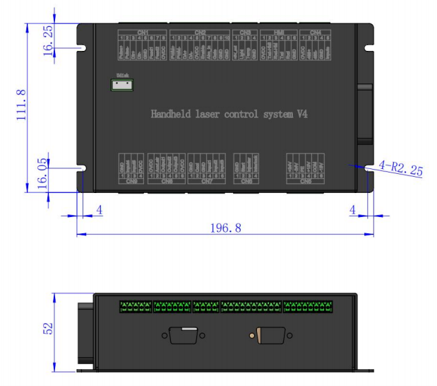
5.1.2 Installation dimension of main board
Overall dimensions : (196.8 * 111.8 * 52) mm
6.1 Electrical material list
Elenco | ||||
|---|---|---|---|---|
S/N | Nome | Illustrazione | Quantità | Osservazioni |
1 | Intelligent double-swing hand-held welding head |  | 1 pezzo | Cellula |
2 | 24V power box |  | 1 pezzo | Cellula |
3 | 15V power box |  | 1 pezzo | Cellula |
4 | Ground wire clamp assembly |  | 1 pezzo | Cellula |
5 | 7-inch display screen |  | 1 pezzo | Cellula |
6 | Touchscreen 6-core connection cable -1.5m- nero |  | 1 pezzo | Cellula |
7 | Handheld laser welding system V4 |  | 1 pezzo | Cellula |
6.2 System wiring
The following figure is a schematic diagram for wiring of the whole system. Refer to the schematic diagram for system wiring. Refer to relevant chapters for detailed interface definition.
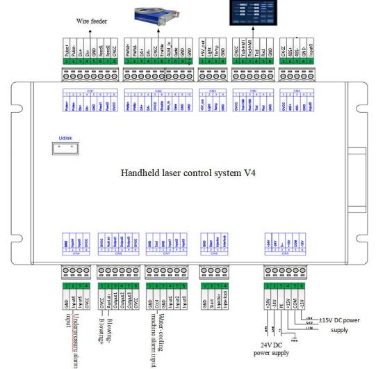
Note: Don't connect the reserved pin in the mainboard.
6.3 CN5 Power Supply Interface
The power supply interface is a 6-pin green terminal, which provides an external power supply interface for the motherboard and galvanometer. The voltages are DC 24V and DC ±15V.
Table 6.3.1 defines the CN5 power supply interface.
Table 6.3.1
Spillo | Segnale | Definizione | Spiegazione |
|---|---|---|---|
1 | 24V+ | Power input | +24V external power supply input, with a power supply input current greater than 2.5A |
2 | 24V- | Power reference ground | -24V external power supply input, with the input current of the power supply exceeding 2.5A |
3 | PGND | External shielded ground | Generally connected to the earth or the casing |
4 | +15 V | Power input | +15V external power supply input, with a power supply input current greater than 2A |
5 | TERRA | Power reference ground | Common terminal of 15V power supply |
6 | -15 V | Power input | - 15V external power supply input, with the input current of the power supply exceeding 2A |
6.4 CN1 Wire Feed Mechanism Interface
The interface CN1 of the wire feeding machine is an 8-pin green terminal, which supports both motor wire feeding and IO wire feeding. Table 6.4.1 provides the definition of the wire feeding machine interface.
Table 6.4.1
Spillo | Segnale | Definizione | Spiegazione |
|---|---|---|---|
1 | Pulse+ | Motor feeding pulse + interface | For wire feeding by the motor, connect to the driver PUL+. |
2 | Pulse- | Motor wire feeding pulse - interface | Motor wire feeding is used, connected to the driver PUL- |
3 | DIR+ | Motor feeding direction + interface | For wire feeding by the motor, connect to the driver with "Dir+". |
4 | DIR- | Motor wire feeding direction - interface | For wire feeding by the motor, connect to the driver Dir- |
5 | TERRA | Reference site | Cellula |
6 | Feed1 | Common terminal of the direct current wire feeding machine | When the direct current wire feeder is feeding the wire, the connection is made |
7 | Feed2 | Direct current wire feeder usually starts operation | When the direct current wire feeder is feeding the wire, the connection is made |
8 | OVCC | +24V power output | Power supply, capable of delivering a maximum output of500mA |
6.5 CN2 Laser Interface
The laser interface is a 10-pin green terminal. The definition of the laser interface is provided in Table 6.5.1.
Table 6.5.1
Spillo | Segnale | Definizione | Spiegazione |
|---|---|---|---|
1 | PWM+ | Modulated signal + | Duty cycle can be adjusted from 1% to 99%, with a 24V level. |
2 | PWM- | Modulated signal - | Duty cycle can be adjusted from 1% to 99%, with a 24V level. |
3 | DA+ | Simulated voltage output + | 0- 10V analog voltage, used for adjusting the peak power of the laser |
4 | DA- | Simulated voltage output - | 0- 10V analog voltage, used for adjusting the peak power of the laser |
5 | OVCC | +24V power output | Power supply, capable of delivering a maximum output of 500mA |
6 | Abilitare | Laser enable signal | 24V voltage level, with the high level being the valid state |
7 | Alarm_in | Laser failure alarm input | Alarm input voltage: 0V |
8 | GATE | Red light indication signal | 24V voltage level, with the high level being the valid state |
9 | TERRA | Massa di riferimento del segnale | Except for DA and PWM, the remaining negative output is... |
10 | TERRA | Massa di riferimento del segnale | Except for DA and PWM, the remaining negative output is... |
6.6 CN3 Temperature Sensor Interface
The temperature sensor interface CN3 is a 4-pin green terminal. Table 6.6.1 defines the interface for the temperature sensor. Users can simply
insert the matching connection cable with the terminals directly.
Table 6.6.1
Spillo | Segnale | Definizione | Spiegazione |
|---|---|---|---|
1 | +5V_out | Sensor P port | +5V power supply, with a maximum output of 500mA |
2 | Leggero | Sensor L port | Cellula |
3 | Temp | Sensor T port | Cellula |
4 | TERRA | Sensor G port | Cellula |
6.7 HMI Touchscreen Interface
The HMI interface is a 6-pin green port. The motherboard supplies power and communicates with the HMI through this port. Table 6.7.1 defines the HMI interface.
Table 6.7.1
Spillo | Segnale | Definizione | Spiegazione |
|---|---|---|---|
1 | OVCC | +24V power output, 500mA | Panel power supply |
2 | TXD_HMI | Receiving end ofthe HMI | RS232 serial port communication TXD signal |
3 | RXD_HMI | Receive from the sending end of the HMI | RS232 serial port communication RXD signal |
4 | TXD | Reserved communication interface | RS232 reserved communication interface |
5 | RXD | Reserved communication interface | RS232 reserved communication interface |
6 | TERRA | Power reference ground | Cellula |
6.8 Reserved Serial Port Interface for CN4
The reserved serial port CN4 interface is a 5-pin green terminal. It remains unconnected. Table 6.8.1 defines the CN4 interface.
Table 6.8.1
Spillo | Segnale | Definizione | Spiegazione |
|---|---|---|---|
1 | OVCC | +24V power output, 500mA | Panel power supply |
2 | 485+ | TXD signal | RS232 serial port communication TXD signal |
3 | 485- | RXD signal | RS232 serial port communication RXD signal |
4 | TERRA | Power reference ground | RS232 reserved communication interface |
5 | Input0 | Reserved input interface | RS232 reserved communication interface |
6.9 CN6 External Startup and Safety Lock Interface
The CN6 interface is a 4-pin green terminal. The definition of the CN6 interface is provided in Table 6.9.1.
Table 6.9.1
Spillo | Segnale | Definizione | Spiegazione |
|---|---|---|---|
1 | TERRA | Reference site | Generally, the start button switch is installed on the welding head - |
2 | Inizio | External start switch input | Generally, the start button switch is connected to the welding joint + |
3 | Injector | Safety latch signal input | This pin must be connected to the safety clamp. Before soldering, attach the safety clamp to the metal material. |
4 | Interlock | Safety lock signal input | This pin must be connected to the nozzle of the handheld head. During the welding process, the nozzle should be brought into contact with the metal material. |
6.10 CN7 General Input Interface 1
The CN7 interface is a 6-pin green terminal of NPN type. The definition of the CN7 interface is given in Table 6.10.1.
Table 6.10.1
Spillo | Segnale | Definizione | Spiegazione |
|---|---|---|---|
1 | TERRA | Reference site | Cellula |
2 | Cool | Water-cooling machine alarm input | NPN type input |
3 | TERRA | Reference site | Cellula |
4 | Input1 | Maintain | NPN type input |
5 | Input2 | Maintain | NPN type input |
6 | Input3 | Maintain | NPN type input |
6.11 CN8 General Output Interface
The CN8 interface is a 6-pin green terminal. By using the OC output, it
can directly drive relays and the maximum current can reach 500mA. The wiring diagram is shown in Table 6.11.1.
Table 6.11.1
Spillo | Segnale | Definizione | Spiegazione |
|---|---|---|---|
1 | OVCC | +24V power output | Power supply, capable of delivering a maximum output of 500mA |
2 | Auxi.air | Gas protettivo | Used for gas blowing control protection, it can directly drive the solenoid valve |
3 | Output1 | Green light | Output 0V in the processed state |
4 | Output2 | Yellow light | Output 0V in standby mode |
5 | Output3 | Luce rossa | Output 0V in alarm state |
6 | OVCC | +24V power output | Power supply, capable of delivering a maximum output of 500mA |
6.12 CN9 General Input Interface 2
The CN9 interface is a 4-pin green terminal of NPN type. The definition of the CN9 interface is given in Table 6.12.1.
Table 6.12.1
Spillo | Segnale | Definizione | Spiegazione |
|---|---|---|---|
1 | TERRA | Reference site | Cellula |
2 | Input4 | Under-voltage alarm input | NPN type input |
3 | Input5 | Maintain | Cellula |
4 | OVCC | +24V power output | Power supply, capable of delivering a maximum output of500mA |
6.13 Galvanometer (Mirror) Interface
The system provides two DB9 galvanometer interfaces, one DB9 male connector and one DB9 female connector.
7.1 HMI function introduction
Handheld laser welding control system operating panel (“HMI” for short) adopts a 7-inch configuration TFT touch screen with beautiful interface and convenient operation. It can set laser related parameters. On the main interface, the input and output IO status, alarm information and motion state can be displayed in real time. Refer to the following figure for the HMI main interface.
Main interface of HMI
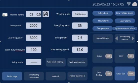
Swing off: to set galvanometer motor swing on or off
Safety lock: to start or close the safety lock. When the lock is started, during the welding, the laser will stop when the welding head does not touch the welding material.
Automatic wire feeding off: to control whether to start automatic wire feeding during welding. It will start automatic wire feeding only when laser emits light.
Emit laser: to start emitting laser or stopping emitting laser
Alarm status area: when alarm signal enables, protective gas low pressure, cool water flow alarm, laser alarm and temperature alarm status will be displayed in real time. When the safety lock is started, its status will be displayed in real time. When the alarm signal is not triggered, the alarm icon is blue; when it is triggered, the alarm icon is blue and red alternately.
Homepage/ Wire feeding parameter/ Diagnosis/ System parameter: to display the type of parameter on the current page. Click an icon to enter the switch of the corresponding parameter page. For instance, if the icon on the homepage turns on, the parameter in the current display area is the parameter of the homepage. When it needs to switch to wire feeding parameter, just click the position of wire feeding, and the icon of this parameter will turn on.
Blowing manually/ Wire feeder: for manual blowing test and the wire feeding and wire withdrawing tests of wire feeder. For example, long press manual blowing key, and it will blow all the time; loosen this key, and it ill stop blowing. For manual wire feeding and wire withdrawing, long press the corresponding small triangle area.
7.2 HMI operation introduction
7.2.1 Parameter setting:
Parameter setting includes: Home page, System parameter, Wire feeding parameter and Diagnosis page
Home page: used to set parameters related to laser, swing and process library when welding.
Process library: click the white box area in process library. The set process library parameter can be selected.
Welding model: to set welding mode, continuous and pulse modes.
Power: to set the peak power of laser when welding
PWM frequency: used to set the frequency of laser PWM modulating signal
Duty cycle: used to set duty cycle of PWM signal with the range from 1% to 100%
Swing frequency: used to set motor swing frequency
Swing length: used to set motor swing length
Wire feeding parameter: used to set system parameter, including wire feeding, slow rise and fall parameters
Light emission time: the time that processing lasts when single point welding mode is set.
7.2.2 Point welding mode
click to enter the single point light emission mode
System parameter: used to set the basic parameters of device. Generally, the setting is performed by manufacturers. Before entering the page, users need to enter password.
System password: 666888
Pulse on time: the time to start light emission in pulse mode
Pulse off time: the time to stop light emission in pulse mode
Slow rise time: used to set the time that the laser analog voltage rises from initial power to the maximum power when it is enabled.
Slow fall time: used to set the time that laser analog voltage falls from the maximum power to initial power when it is stopped.
Light on power: used to set the initial power of laser, the percentage of welding power
Light on asymptotic time: the time to control the light on power of laser to rise slowly to the set power
Light off power: used to set the light off power of laser, the percentage of welding power
Light off asymptotic time: the time to control the light off power to fall slowly
Language: to switch language
Advance gas on delay: when starting processing, users can set gas activation delay. When the external start button is pressed, after blowing delay for some time, the laser can emit light.
Gas off delay: when stopping processing, users can set gas closure delay. When processing is stopped, stop the laser first. After delay for some time, stop gas blowing.
Automatic swing: used to set whether the galvanometer swings automatically.
When automatic swing function is enabled and the safety lock is connected, But if the safety lock is not connected, make the motor not carry out automatic swing after delay for some time.
Device parameter: used to switch to the device parameter page. It requires password.
Authorization: for the authorization management of mainboard
Device number: used to set the bluetooth number of control system. When users have multiple devices, they can define the number for management.
Offset in middle: for the setting of the offset in middle of red light.
7.2.3Wire feeding parameter
used to set parameters related to wire feeding, wire supplement and withdrawal.
Wire withdrawal speed: the wire withdrawal speed of motor when the start button is loosened.
Wire withdrawal time: the time for motor wire withdrawal
Wire supplement speed: the speed of motor wire supplement
Wire supplement time: the time for motor wire supplement
Wire feeding delay time: wire feeding after light delay for a period, generally it’s 0.
Continuous wire feeding: used to change wire for the wire feeder. Click once for continuous wire feeding, click again to stop it.
Continuous wire withdrawal: used to change wire for the wire feeder. Click once for continuous wire withdrawal, click again to stop it.
Diagnosis: to monitor the IO status of current system
7.2.4Device parameter
used to set parameters related to device
Laser rated power: used to set the rated power of laser
Maximum deflection angle of galvanometer: used to set the range of the maximum deflection angle of galvanometer.
Maximum frequency: set the maximum frequency of laser PWM signal. When PWM frequency set by welding parameter exceeds the maximum frequency, the frequency will be limited to the maximum value.
Maximum swing length: set the maximum length during swing. When the length set by welding parameter exceeds the maximum length, the length will be limited to the maximum length.
Wire feeding step: used to set the step during motor wire feeding.
Direction of motor wire feeding: used to set the direction polarity of motor wire feeding.
Galvanometer correction coefficient: when there is a nuance in the set length and the actual length, it can be modified by this parameter. When there is no need for
correction, it is usually set as 1.
Lens temperature alarm enable: enable lens temperature alarm. When the temperature exceeds the limited value, the alarm signal will be generated.
Lens temperature alarm limited value: the limited value of lens temperature
Laser alarm enable: used to enable laser alarm. When laser generates alarm, the alarm signal will be generated.
Laser alarm level: used to set laser alarm to trigger the level logic.
Water-cooling machine alarm enable: used to enable water cooling machine alarm. When the water cooling machine generates alarm, the alarm signal will be generated.
Water-cooling machine alarm level: used to set water-cooling machine alarm to trigger the level logic.
Low pressure alarm enable: used to enable gas alarm. When gas low pressure generates alarm, the alarm signal will be generated.
Low pressure level: used to set low pressure alarm to trigger the level logic.
8.1 Introduction to Pulse Dotting Mode
【Main Page】 → 【Welding Mode】 → 【Pulse Dotting】
The dotting on-off time and off-on time of the dotting mode can be modified. Dotting on time: The time interval for laser emission.
Dotting off time: The time when the laser is off during dotting.

9.1Temperature parameter setting of Protective Lens
[Home Page]→ [System Parameter]→ [Equipment Parameter]→ [Input Password: 666888] →next page→ lens temperature alarm limit value.
It is suggested to set the set value of lens temperature to 50. After the lens temperature exceeds the set value, the alarm caution will arise on the home page and the display light on the side of the handheld plumb joint will turn to red.

10.1 The schematic diagram for replacement of part of the structure is asfollows
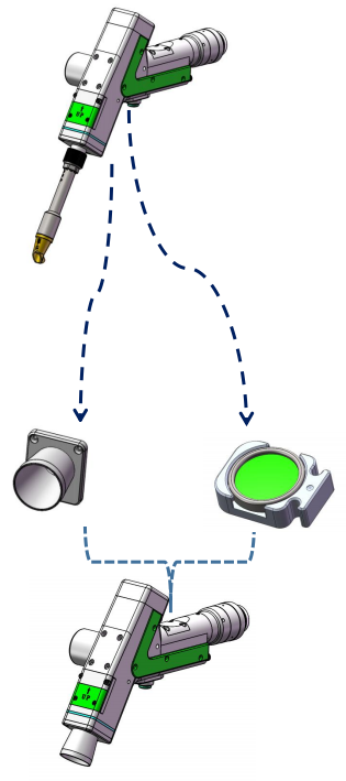
10.2Module replacement
[Wire Feed Holder Module]: Loosen the 2-M3 screw to take out the module (Figure 1)
[Brass Nozzle Connecting Base]: Loosen the 3-M2.5 screw to take out the module (Figure 2)
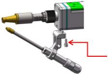
Figura 1

Figura 2
10.3 Assembly and Replacement
[Jacket Installation]: Installation pursuant to the sequence-1, 2 and 3.
[Installation of Focus Drawer]: Loosen the 4-M2.5 screw to directly draw out the focus module. Notice the small dot in the middle is in the upper part when the focus module is replaced and cleaned. The welding focus module replaced shall be subject to dustproof protection for use and replacement.

11.1 Select processing type
As for the welding mode switching to 100mm cleaning mode, inputting password-666666 will be reminded by clicking [Processing Type] on the panel pursuant to [System Parameter]->[Authorization]->[Processing Type]. After the password is put correctly, enter the system type selection interface, as shown in the figure:

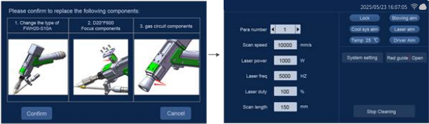
11.2 Hint of module replacement
After the user chooses the processing type, the system shall use the text and picture for prompting for the gun head component to be replaced. The system will remind power-on anew by clicking [Confirm] after the user confirms the corresponding hardware components and replacement conditions. The equipment is powered down by the use interface to replace the corresponding component.
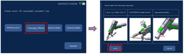
11.3 Switch completion
After the replacement of hardware component by the user is over, the equipment can be powered on anew. Whether you confirm the replacement of the hardware component will be reminded again at the moment. The user shall click [Confirm] after confirming the replacement of component is over and the system processing mode switch will be over.
12.1 The schematic diagram for replacement of structure is as follows:
Remove the welding nozzle and replace the special nozzle for welding seam cleaning.
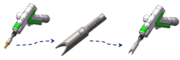
12.2 System switching
The system is easy to switch, and the maximum width of welding seam cleaning is 12 mm.

13.1 The schematic diagram for replacing the structural part is as follows:
Remove the 3 *M 2.5 * 6 hexagonal socket head screws of the welding gas ring (using a 2mm hexagonal wrench), replace the specialized energy storage welding nozzle assembly, and use the 3 *M 2.5 * 6 hexagonal socket head screws (using a 2mm
hexagonal wrench) for installation.

13.2 System switching:
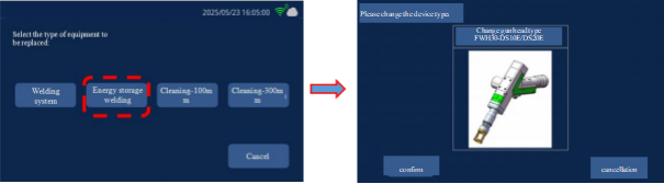
Taking the example of switching from welding mode to energy storage welding mode, on the panel, follow [System
Parameters] ->[Authorization] ->[Processing Type], click on [Processing Type], and a password of 666666 will be prompted. When the password is entered correctly, the system type selection interface will be entered, as shown in the figure:

13.3Module replacement prompt
After the replacement of hardware component by the user is over, the equipment can be powered on anew. Whether you confirm the replacement of the hardware component will be reminded again at the moment. The user shall click [Confirm] after confirming the replacement of component is over and the system processing mode switch will be over.
14.1 This section describes the HMI function
Handheld laser welding control system operating panel (“HMI” for short) adopts a 7-inch configuration TFT touch screen with beautiful interface and convenient operation. It can set laser related parameters. On the main interface, the input and output IO status, alarm information and motion state can be displayed in real time. Refer to the following figure for the HMI main interface.
Main interface of HMI

【 Scanning Parameters 】 : It is used to set the relevant parameters during galvanometer scanning processing.
Parameter number: The system supports the storage of 9 groups of parameters.
Scanning speed: Used to set the scanning speed of the galvanometer.
Laser power: Set the output light power during welding.
Scanning length: It is used to set the length of the laser scanning in the X direction.
Scanning width: It is used to set the width in the Y direction of the laser scanning.
Scanning type: It is used to set 5 types of scanning waveforms, supporting
circular, rectangular, single straight line, spiral circle, and multiple straight lines
——
+
The number of scans: When the start button is continuously pressed to emit light, the maximum number of scans before the light emission stops. If it is ∞ times, it will loop infinitely until the start button is released.
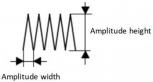
Linear selection: Set four differentiated linear types, and multiple scanning waveforms can be formed through scanning types. Supports helix, sawtooth, point, and spiral point When blank is selected, the linear type is not enabled


Pitch: The pitch when the linearity is set to helical. The linearity is a dedicated parameter for the helical mode.
Spiral diameter: The spiral diameter when the linearity is set to spiral, and the linearity is the dedicated parameter for the spiral mode.
Amplitude height: Set the linearity to the tooth height when the linearity is serrated, and the linearity is a dedicated parameter for the serrated mode.
Amplitude width: Set the tooth width when the linearity is set to sawtooth, and the linearity is the dedicated parameter for the sawtooth mode.
Number of points: The quantity of light output dots when selecting points or spiral points for the line.
Helical circle pitch: The distance between helical lines when the helical point is linearly selected or the swing type is a helical circle.
Large circle diameter: When the swing type is set to spiral circle, it is the length of the maximum diameter of the spiral circle and a dedicated parameter for the spiral circle mode.
Small circle diameter: The length of the minimum diameter of the spiral circle when the swing type is set to spiral circle, a dedicated parameter for the spiral circle mode.
Number of parallel lines: When the swing type is parallel lines, the number of single-sided lines of the parallel lines, the number of main lines = number of parallel lines * 2.
Parallel line spacing: The spacing of parallel lines when the swing type is parallel.
Light output time: Set the light output time of each point when the linearity is a point, and the linearity is a dedicated parameter for the point mode.
【 Alarm Status Area 】 : Once the alarm signal is enabled, it will display in real time the low pressure alarm of the protective gas, the cold water flow alarm, the laser alarm, the temperature alarm, and the galvanometer status. When the safety lock is enabled, the safety lock status will be displayed in real time. When the alarm signal is not triggered, the corresponding alarm state is in blue. When an alarm occurs, the corresponding alarm icon will flash alternately in red and blue.
【 System Parameters 】 : Click to enter the system Settings page and modify the system function parameters.
【 Red Light | On/Off 】 : The red light switch can control the switch indicated by the red light of the laser.
【 Allow/Prohibit | Laser Emission 】 : This button can be used to allow or prohibit laser emission.
When light emission is allowed, pressing the start light emission button will emit laser for welding. When the light output is prohibited, pressing the start light output button will not result in laser welding.
【 Manual Blowing 】 : Clicking on the manual blowing area will continue the blowing process. Clicking on it again will turn off the blowing.
14.2 HMI operation introduction
System parameter Settings: After parameter modifications, they need to be saved to take effect.
Early vent time: When starting the processing, a delayed vent can be set. When the external start button is pressed, air is blown and delayed for a period of time, and then the laser starts to come out.
Delayed gas shut-off time: When processing stops, a delayed gas shut-off can be set. When processing is stopped, first stop the laser output, delay for a period of time, and then stop the air blowing.
Opening power: It is used to set the initial power of the laser, which is a percentage of the welding power.
Progressive opening time: Controls the time it takes for the laser's output to slowly rise to the set power.
Light-off power: It is used to set the light-off power of the laser, which is a percentage of the welding power.
Progressive turn-off time: The time used to control the slow decrease of the laser's turn-off power.
Language: Used for switching languages.
The length of the early deceleration: Control the distance of the early deceleration in the gradual time of turning off the light.
Laser frequency: Used to set the PWM frequency of the laser.
Duty cycle: Set the duty cycle of the PWM modulation signal, with the setting range being 1% ~ 100%. (switch the parameters within the display interface)
Double-click light output enable: Select the light output mode and whether to double-click the button. If not enabled, click the button
Enable security lock: Select whether to perform security lock protection.
Proportional coefficient: It is used to set the maximum range ofthe X-axis and
Y-axis of the galvanometer. This parameter needs to be consistent with the actual range of the galvanometer; otherwise, the actual light output length and width may not be accurate. The default parameter does not need to be set.
Field lens type: Reserved for switching between different field lenses. Reserved parameters do not need to be set.
【 Device Parameters 】 : It is used to switch to the device parameters page and requires entering the password 666888. Pulse on time: the time to start light emission in pulse mode
【 Authorization 】 : Perform the operation of reading and decrypting the authorization code, as well as display the relevant information of the panel and motherboard version number.
【 Center Offset 】 : Used for setting the center offset of red light.
Multi-level parameters: During welding, the parameter 1 used during the current welding process will be automatically used as parameter 2 for the next welding operation.
Quantity: Used to set the number of corners to be scanned during the scan process, applicable to ' '
14.3 Equipment Parameters
【 Device Parameters 】 : It is used to set the maximum and minimum values of the restricted parameters. These parameters will restrict the laser parameters.
Password input is required to enter. After parameter modification, it needs to be saved to take effect.
Maximum scanning speed: Used to set the maximum galvanometer swing speed Minimum scanning speed: Used to set the minimum galvanometer swing speed Maximum scan length: Used to set the maximum scan length allowed by the device
Minimum scan length: Used to set the maximum scan length allowed by the device
Rated power of laser: It is used to set the rated power of the laser
Maximum laser frequency: Used to set the maximum laser frequency
Minimum laser frequency: Used to set the minimum laser frequency
Laser alarm enable: It is used to set whether to enable laser alarm. When enabled, a laser alarm prompt will be generated when the laser alarm input triggers the alarm.
Laser alarm level: Used to set the logic of the laser alarm trigger level.
Water cooling machine alarm enable: It is used to set whether to enable the water cooling machine alarm. When enabled, when the water cooling machine alarm input triggers the alarm, an alarm prompt for the water cooling machine will be generated.
Alarm level of water cooler: It is used to set the logic of the alarm trigger level of the water cooler.
Under-voltage alarm enable: It is used to set whether to enable the gas under-voltage alarm. When enabled, a under-voltage alarm prompt will be generated when the under-voltage alarm input triggers the alarm.
Under-voltage alarm level: Used to set the logic of the under-voltage alarm trigger level.
Temperature alarm enable: Enable the lens temperature alarm. When the temperature exceeds the limit value, an alarm signal will be generated.
Temperature alarm limit value: Lens temperature limit value.
14.4 Alarm Information
The alarm information includes: safety clip alarm and machine alarm.
The safety clamp alarm is caused by the safety clamp not being reliably connected to the cleaning head.
The machine alarms include three types: laser alarm, water-cooling machine alarm and low voltage alarm. In the alarm information interface, multiple alarm messages can be displayed, with a maximum of 3 pages. They can be switched between the previous page and the next page.
When the alarm is triggered, the laser output will be stopped at this time, the galvanometer will stop moving, and the corresponding alarm information will be prompted. Users can check the relevant hardware problems and clear the alarm according to the alarm prompt. After the alarm is cleared, the alarm record of the machine's alarm will still exist in the alarm information. At this time, you can manually clear the alarm by entering the alarm information interface. If the alarm is not cleared, it will continue to prompt when the alarm is manually cleared.
(Gun head light emission control logic: Click the switch button to preview the graphic with red light. After clicking, continuously double-click the switch button to emit laser.)
15.1 Function Introduction
The RDWelder mobile APP is an application suitable for remote control of handheld welding products, supporting various types of product applications such as single pendulum welding, double pendulum welding, single pendulum cleaning, and double pendulum cleaning. Users can connect the board card through this APP to achieve the purpose of wireless connection control. It can effectively solve the problem of the processing station being far from the equipment and constantly traveling back and forth. It supports remote viewing of equipment status and parameter adjustment, facilitating equipment management and maintenance. The APP also has rich technical center resources. It is provided for customers to install and maintain equipment, review process data, assist in troubleshooting, and refer to application cases.
15.2 Equipment connection
15.2.1 Connection mode
The handheld APP and control card support two connection modes : AP mode and STA mode.
In AP mode, the APP is directly connected to the control card. The control card emits a WIFI hotspot signal. Customers can use mobile devices such as mobile phones to connect to the WIFI hotspot signal emitted by the control card. After the connection is completed, the board card can be controlled using the APP. Both the touchscreen and the APP use WIFI ICONS for status display.

·In STA mode, the APP and the control card are connected to the cloud via the Internet. After setting the control card to STA mode, it is necessary to connect to WIFI to access the network. Access the server through traffic data to obtain the device status and perform operation control. Both the touchscreen and the APP use Internet of Things cloud ICONS for status display.

15.2.2 AP mode connection
Board card Settings:
·Click the upper right corner of the touch screen to enter the WIFI configuration page and configure the WIFI hotspot.
·Set the connection mode to AP and set the name and password of the WIFI hotspot. If the WIFI is turned on, you need to first click the < Turned On > button to turn off the WIFI. When the WIFI icon goes off, you will enter the configurable WIFI setting state.
·After the configuration is completed, click the < Turn on WIFI> button, and the system will turn on WIFI again.
·After the WIFI hotspot configuration is completed, the WIFI configuration mode will be turned off, the WIFI icon will light up, and the mobile phone APP can connect to the WIFI on the board card.

APP Settings:
·Click the icon on your mobile phone to launch the APP.
·The device connection status in the upper left corner of the motor enters the < Device Management > page.
·Select the direct connection of the device, enter the phone Settings page to set up the WIFI connection, and connect to the WIFI hotspot of the control card.
·After the connection is completed, you can enter the APP to check that the mobile APP has been connected to the device.
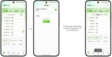
15.2.3 STA mode connection
Board card Settings:
·Click the upper right corner of the touch screen to configure the WIFI hotspot and enter the WIFI configuration page.
·Set the connection mode to STA and connect to an external WIFI. If the WIFI is turned on, you need to first click the < Turned On > button to turn off the WIFI. When the WIFI icon goes off, you will enter the configurable WIFI setting state.
·After the configuration is completed, click the < Turn on WIFI> button, and the system will connect to an external WIFI.
·After the WIFI connection is completed, the WIFI configuration mode will be turned off, the remote icon will light up, and the device will be in an online state.
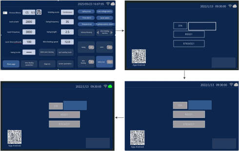
APP Settings:
Click the icon on your mobile phone to launch the APP.
The device connection status in the upper left corner of the motor enters the < Device Management > page.
You can view the added cloud devices on the device management page. The highlighted cloud logo indicates that the device is online, while the grayish-white status indicates that it is offline.
After selecting the online device, click "Connect" to complete the device connection.

Note: The STA mode requires users to register an account and then add the device serial number to their personal account before remote management can be carried out.
15.3 APP download method
Android:

https://mantisolo.com/versionQrCode.html?qrform=6a7a15d4f48d72e6e 02b0b14af8e3bc15&company_code=003&platform=APP
Apple : Search for "RDWelder" in the App store
15.4 APP function
Welding mode
Modalità di pulizia

The RDWelder mobile APP supports single pendulum welding, single pendulum cleaning, double pendulum welding and double pendulum cleaning. After the APP is connected to the board card, it can automatically adapt to the current processing mode of the control card.
Welding mode :
[Home Page] : Supports management of process parameters, processing status, blowing adjustment, and wire feeding control. The entry to < Technology Center > is located in the upper right corner.
【 Process 】 : Welding process library, where users can manage process parameters.
【 Diagnosis 】 : Manage the status of the equipment, support the query of alarm records, and enable central correction.
【 Settings 】 : Go to the parameter setting page to manage ordinary setting parameters. You can enter the authorization management. After entering the password, you can manage advanced parameters.
[My] : Personal user page for managing personal information. Cleaning mode :
[Home Page] : Supports management of process parameters, processing status, and blowing adjustment. The entry to < Technology Center > is located in the upper right corner.
【 Diagnosis 】 : Manage the status of the equipment, support the query of alarm records, and enable central correction.
【 Settings 】 : Go to the parameter setting page to manage ordinary setting parameters. You can enter the authorization management. After entering the password, you can manage advanced parameters.
[My] : Personal user page for managing personal information. Style.
16.1 Function Introduction
The smart cloud system enables devices to access the Internet, allowing users to view the device status on the web page for remote management.
16.2 Smart Cloud Login
By visiting https://fiot.chanelink.com/ address, see page client login page, the following figure, the user account login, new user registration, password can be recovered, and so on.
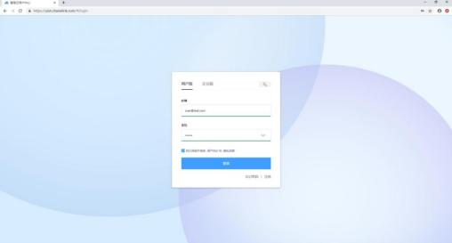
16.3 User Center
After successful login, you will be redirected to the home page of the User Center, as shown in the following figure. Users can view the added application functions, such as device management, My Profile, remote assistance, technical support, etc.
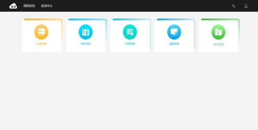
My application, as seen in the above picture, the one added by this user, can manage the added applications.
Application Center, where applications can be added.
Personal information, click this button to go to my profile, you can modify person information.
Log out. Click this button to exit to the login page.
16.4 Equipment Management
In "My Applications", click on "Device Management" to jump to the "Device Management" page, as shown in the following figure.
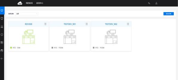
The left side is the menu bar, which opens the device monitoring page by default. The device nickname entered when adding the device.
The connection status of this device indicates whether the device is connected to the Internet.
Equipment operation list (expands when the mouse hovers).
The equipment operation list has the functions of editing, detailing and unbinding. The device can be edited, unbound and details viewed.
The "Add Device" button allows you to add devices to your personal account.
16.5 Remote assistance
In "My Apps", click on "Remote Assistance" to be redirected to the Remote assistance page, as shown in the following figure.
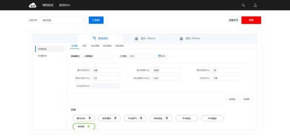
You can view the devices under the added personal account in the device list. After confirming the need for a remote assistance device, a remote connection can be made to check the device status and manage parameter configuration.
16.6 Technology Center
In "My Applications", click on "Technical Support" to be redirected to the technical support page, as shown in the following figure.
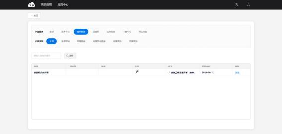
On the technical center page, you can query various product information, including downloading instruction manuals and viewing application videos in the download center.