









·Operate this machine while wearing any metal objects (i.e., rings, watches, bracelets, etc.) that may come into contact with the Upper Tool, Lower Tool or work piece.
·Tamper with any part of this machine ’s electrical system unless you are a trained electrician and thoroughly understand this machine ’s electrical schematic.
·Attempt to test or demonstrate this machine ’s Safety System by placing any portion of your hand or body between the Upper and Lower tools.
·It is forbidden to load more than 22Mpa when using the device. Work pressure is shown above the pressure table.
·Do not step foot pedal when placing any portion of your hand or body between the Upper and Lower tools
·It is prohibited to attempt to press the work piece with irregular shape.
1、 Equipment parameters
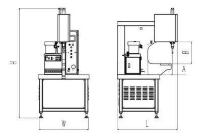
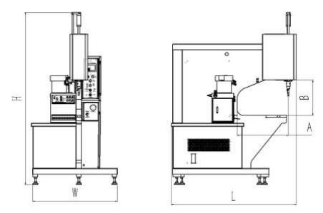
weight of machine with wooden box
machine type | M618-NC | M1025NC |
|---|---|---|
weight (Kg) | 650 | 1100 |
W× L×H(cm) | 93 × 110×200 | 107×156×220 |
Pressure(KN) | 2~57 | 6~97 |
Deep throat A(cm) | 45 | 65 |
Throat height B(cm) | 40 | 45 |
M618-NC
M1025-NC
2、 Unpacking and installation
Our company's wooden crate adopts a panel structure, which is a new type of packaging that can be reused repeatedly. After use, most of it can be recycled, which is conducive to the recycling of resources and the protection of the environment.
1. Dismantling
2-1-1. Use a forklift to transport the container to the designated location.
2-1-2. Remove the outer packaging (wooden box) of the equipment.
2-1-3. Remove the wooden board that fastens the foot cup of the equipment base.
2-1-4. Use a forklift to lift the equipment, or use a lifting rope that matches the weight of the equipment to lift it through the lifting port on the top of the equipment.
(Figure 2.1)
1-5. Remove the wooden pads of the equipment and carefully place the equipment on the ground.
2. Install equipment
2-2-1. Information on installation/usage environment:
Environmental temperature: 0 ℃ -40 ℃;
Humidity: 40 ° C, ≤ 50%; 20°, ≦90%;
(Higher humidity is allowed when the temperature is low); Altitude: ≤ 2200m.
2-2-2. Adjust the level of the equipment by adjusting the height of the four foot cups. After adjusting the level of the machine, please tighten the foot cup nut.

Figure 2.1
3、 Power settings
Connect the wires between the equipment and the factory
1、Check the voltage on the machine nameplate, make sure the machine ’s incoming shop voltage is the same as the voltage the machine has been wired for. If the voltage do not match, stop! Contact your TILLO representative for instructions on how to proceed.
2、 Ensure that the machine ’s electrical power supply has been disconnected at the supply source. Turn the machine ’s Main Disconnect Switch to the Off position. (see Figure 3. 1)
3. Connect three wires with L1, L2, and L3 identification tubes in the power cord connected to the device, and connect them to the three-phase power supply of the factory
Connect three live wires. If the motor rotates in the opposite direction, any two live wires need to be swapped. Connect the wire with an N identification tube to the factory's neutral wire. Some voltage levels do not require a neutral wire. Wires with PE identification tubes are connected to the factory's ground wire.
Atenção |
|---|
·Power cable need use qualified wire ·Check to make sure that the electrical power supply for this machine has been disconnected at the supply source before doing any work on the machine ’s electrical system |
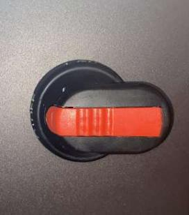
Figure 3.1 Main Disconnect Switch on the Off position
4、 Equipment Introduction
1. Equipment appearance structure
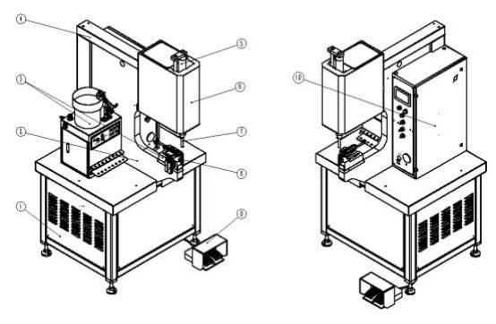
①frame and hydraulic station
②C frame
③autofeed system
④hose cover
⑤cylinder stop nut
⑥hydraulic cylinder and cover
⑦upper tool holder
⑧lower tool holder
⑨foot switch
⑩electrical cabinet and operation panel
2. Operation panel
4-2-1 Introduction to Operation Panel
Stroke counter
Once fastening, the counter counts once, This is to track the total number of fastening products to facilitate the use of the equipment.
Buzzer
When the equipment malfunctions or riveting is completed, a buzzing sound is emitted.
Indicador
Show power on-state(White or Green)
Power on
Press the switch, green light is on, start the pump motor; Press the switch again, the light becomes dark and the oil pump motor stops.
Parada de emergência
In an emergency, press this switch to return upper tool to its highest position and then stop the pump motor. Reset the switch when restarting the device.

Voltage regulating switch
Turn the pressure regulating switch to the left and press the right foot switch to adjust the pressure. After adjusting the pressure, turn the pressure regulating knob to the right and perform normal riveting
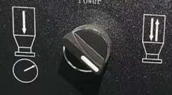
Figure 4.3
operation mode
On conductive mode(figure5.2), the machine protection induction voltage (24V) is opened. When the upper and lower tool are in contact, the control circuit system shall check whether the protection voltage is connected; If connected, the machine will continue to work, whereas the machine will return the upper tool, and the fastener will not be riveted into the workpiece.
On non-conductive mode(figure5.3), When the upper and lower tool are in contact, the control circuit will stop lower tool pressing movement, the operator needs to step on the right foot switch again, the lower tool will continue to press down.
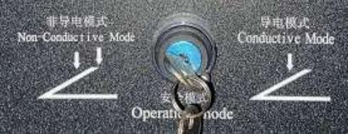
Figure 4.4
auto feed mode
Choose autofeed mode Ⅰ :feed studs,screw and nut.
Choose autofeed mode Ⅱ:feed nut and short studs(below 4.5mm)
Medidor de pressão
Shows system pressure, the maximum cannot exceed 22Mpa when adjusting pressure
Controle de pressão
Adjust the pressure according to the fastener riveting force; Adjust clockwise, the system pressure becomes larger whereas it will be smaller.
Note:When testing up machine, The pressure should be adjusted to the minimum, then increase slowly.
4-2-2 Auto feed system(option)
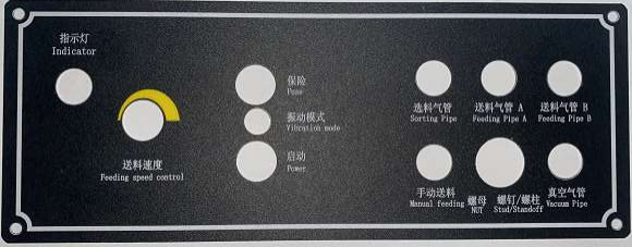
Figure 4.5
velocidade de alimentação
Turn the knob clockwise will increase feeding speed of vibration bowl.
Turn the knob counter-clockwise will decrease feeding speed of vibration bowel.
Note: different fastener need different feeding speed, which is subject to sending fastener to entrance.
Fusível
Use 4A glass tube fuse, prevent current overload.
Vibration mode
According to the vibration mode, it is divided into full wave and half wave, and in general, full wave mode is used.
Turning the switch to the right is half wave mode, and vice versa is full wave mode.
Full wave mode, smooth vibration, suitable for rivets with relatively small mass; In half wave mode, the rivet jumps significantly during vibration, making it suitable for rivets with relatively large masses.
The vibration mode is divided into full wave and half wave mode, normally use whole wave mode.
Poder
Vibration bowel power
Sorting pipe
Pipe interface of sorting cylinder
Feeding pipe A/Feeding pipe B
Pipe interface of feeding cylinder, to the A/B interface.
Manual feed
Press 0.5 ~ 1 second, the system automatically sends the fastener to the automatic tool position. This function is used when debugging automatic feeding tools and lack of fasteners.
vacuum switch
Select whether the current feeding mode need vacuum
Upper feeding studs or screw, need open Vacuum.
Manual feeding or Automatic lower feeding nut, need close Vacuum.
Vacuum tube
Pipe interface of upper tool, upper feeding studs or screw, need use interface.
3. Equipment program
4-3-1. Power on page
After starting the machine, enter the boot page (Figure 4.6),
Pop up the anti pressure hand alarm window (Figure 4.7). At this time, you need to lift the anti pressure hand network once, confirm that the anti pressure hand function is normal, cancel the alarm, and click to enter the system;
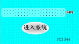
Figure 4.6
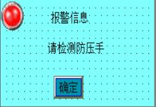
Figure 4.7
4-3-2. Maintenance page
Display device number and lock, contact the manufacturer to obtain a random code, which can unlock the machine's usage period;
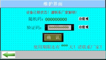
Figure 4.8
4-3-3. Operation page
workpiece counter
Set Numbers according to the number of fastener times for individual parts. Once fastening, the counter counts once, after the setting number is reset to zero counting, and the buzzer alarm prompts to prevent the leakage of the parts
stroke counter
Once fastening, the counter counts once, This is to track the total number of fastening products to facilitate the use of the equipment
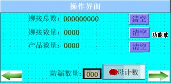
Figure 4.9
4-3-4. Adjustment page
Tempo de permanência
Control the pressure time of the upper tool to the product, prevent the material toughness rebound and lead to the insertion not tightly. Adjust clockwise to extend the pressure time; Whereas , it will be shorter.
Up travel
Control the position that the upper tool return to after an insertion is completed. Adjust clockwise to heighten the up travel ; Whereas , it will be lower.
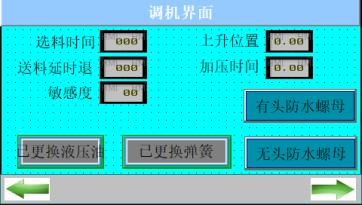
Figure 4.10
4-3-5 Input/Output Page
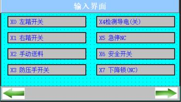
Figure 4.11
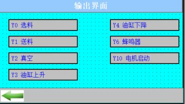
Figure 4.12
4-3-6 Alarm page

Figure 4.13
4-3-7 Factory settings
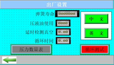
Figure 4.14
4、foot pedal
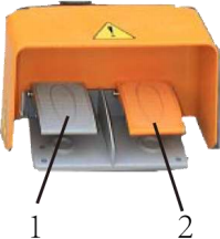
Figure 4.15
he foot pedal is used to operate the upper and lower motion of upper tool.
Left foot pedal: upper tool moves up
Right foot pedal: upper tool moves down
1.left foot switch
2. right foot switch
5、Patented security system
4-5-1、structure
1 connection rod 2 Conductive copper needle 3 spring 4.safety switch 5.snap spring 6.slide screw 7.upper tool connection base 8.upper tool set screw 9.upper tool punch head
4-5-2、operation mode
conductive mode
Switch the operation mode to Conductive mode on operation panel.(figure 4.4)
When punch head contacts products, the system to test for a conductive parts products, if the product is conductive parts, the upper punch continues down, finish the action and return to set position; If the product is not conductive, the upper punch will be immediately up and back to set position safety.
non-conductive mode
Switch the operation mode to Non-Conductive mode on operation panel.(figure 4.4)
Whether product for conductive parts, When head contacts products,, the upper punch will immediately stop ,need step right foot switch again , the upper punch continues down, finish the action and return to set position.
4-5-3、operating principle
When oil cylinder piston rod fall until upper punch contacts product, the connecting rod and upper tool connection base can produce relative sliding, trigger the safety switch (the upper tool connection base can overcome the spring pressure and rise 6.5 mm), gives the signal starting test whether conduction between upper and lower tool punch, to determine whether products between upper and lower tool is conductive.
Aviso | When in non-conductive mode, do not step right foot switch two times when any part of your body is close to the tool. |
5、 Security testing
Aviso | Must test the safety System at the beginning of each work. Never attempt to test or demonstrate this machine’s Safety System by placing any portion of your hand or body between the Upper and Lower tools. |
1、safety system testing
5-1-1、Power on
Turn the main disconnect switch to the On position, the green On light will turn on.
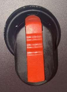
Figure 5.1 Turn the main disconnect switch to the On position
Note: main disconnect switch is on the back of Electrical Cabinet.
5-1-2、start the moor
Press Start button to run the motor.
Note:If can not start the motor, it is possible that the "emergency stop" switch on the operation panel has been
pressed, please clockwise rotate the "emergency stop" switch, turn 90 degrees, the urgent stop switch pops up, press the "start" button again to start the oil pump motor.
5-1-3、Select the couctive mode
Switch the operation mode to Conductive mode on operation panel.(figure 4.4)
5-1-4、adust the ram travel
Adjust the ram travel to the Max.
5-1-5、raise upper Yool holder
Step on the left foot switch to raise the upper tool until the distance between the upper and lower tool is about 100mm
If any discrepancies appears, the security system fails! Immediately press the "emergency stop" switch on the operation panel to switch off the machine, Turn the main t switch to the OFF position and contact the relevant personnel for repair. Do not operate the machine until the machine is repaired and the safety system is tested good.
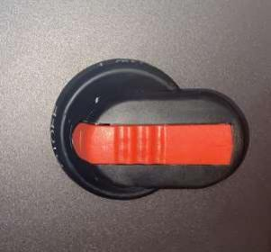
Figure 5.2 Turn the main disconnect switch to the On position
2、conductive mode test
5-2-1、power on and start pump motor
The operation method can be found in 5-1-1 and 5-1-2.
5-2-2 、Slect the conductive mode
Switch the operation mode to Conductive mode on operation panel.(figure 4.4)
5-2-3 、Adjust dwell time
Adjust the "dwell time" knob on the operation panel to adjust the knob clockwise to 1/2 laps
5-2-4、Adjust pressure
Step on the left foot switch to raise the upper tool to the Max. Turn "pressure control" button on the operation panel, adjust the pressure to 1 mpa (pressure gauge show 1 mpa)
5-2-5、testing
Place the conductive material (such as or paper) on lower tool, confirm the material completely covered on the top. Step on the right foot switch, the upper tool moves down, and contacting the non-conductive material, the upper automatically rises back to the set height
Take away conductive material, step right foot switch, the upper tool moves down, after contact lower tool, the upper tool will rise, after a certain amount of dwell time, it automatically rise back to set height
The above phenomenon indicates that the conducting mode is normal.
3、non-conductive mode test
5-3-1、power on and start pump motor
The operation method can be found in 6-1-1 and 6-1-2.
5-3-2、Select the non-conductive mode
Switch the operation mode to non-conductive mode on operation panel.(figure 4.4)
5-3-3 、Adjust dwell time
Adjust the "dwell time" knob on the operation panel to adjust the knob clockwise to 1/2 laps
5-3-4 、Adjust pressure
Step on the left foot switch to raise the upper tool to the Max. Turn "pressure control" button on the operation panel, adjust the pressure to 1 mpa (pressure gauge show 1 mpa) will return to 1Mpa after a certain amount of dwell time, it automatically rise back to set height.
The above phenomenon indicates that the non- conducting mode is normal.
Aviso | When in non-conductive mode, do not step right foot switch two times when any part of your body is close to the tool. |
6 set up machine
1、power on and start the motor
The operation method can be found in 5-1-1 and 5-1-2.
2、Adjust pressure
Step on the left foot switch to raise the upper tool to the Max. Turn "pressure control" button on the operation panel and check pressure gauge, adjust the pressure to setting value, Loosen foot switch after setting pressure.
3、tooling alignment
6-3-1、Adjust pressure
Step on the left foot switch to raise the upper tool to the Max. Turn "pressure control" button on the operation panel to adjust pressure to Min.
6-3-2、Adjust upper and lower tool to be coaxial
Step on the right foot switch to move the upper tool down until it is about 2mm from top to lower tool. Through visual observation, observe whether the upper and lower tool are coaxial, if not coaxial, by adjusting the position of the lower tool holder, the upper and lower tool come to
4、adjust up travel
The insertion mode of normal fastener only need adjust pressure and dwell time. But for soft base material riveting, it is necessary to limit the height of the upper tool, that is, adjust the top limit nut of oil cylinder
7、options
1、hand tool
7-1-1、studs hand tool
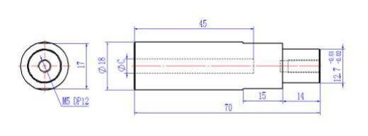
studs hand tool list | ||
|---|---|---|
tipo | C | qty |
SO-M3 | 4.26 | 1 |
SO-3.5M3/M3.5 | 5.45 | 1 |
SO-M4 | 6.06 | 1 |
SO-3.5M4/M5 | 7.18 | 1 |
7-1-2、nut hand tool
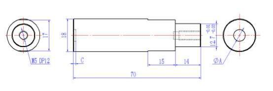
nut hand tool | |||
|---|---|---|---|
tipo | UMA | C | qty |
S-M3 | 6.5 | 1.4 | 1 |
S-M4 | 8.1 | 1.9 | 1 |
S-M5 | 9.0 | 1.9 | 1 |
S-M6 | 11.3 | 3.98 | 1 |
S-M8 | 12.9 | 5.37 | 1 |
7-1-3、screw hand tool
screw hand tool | |||
|---|---|---|---|
tipo | UMA | C | qty |
FH-M3 | 3.6 | 3.03 | 1 |
FH-M4 | 4.6 | 4.03 | 1 |
FH-M5 | 5.6 | 5.03 | 1 |
FH-M6 | 6.6 | 6.03 | 1 |
FH-M8 | 8.6 | 8.03 | 1 |
Standard upper tool punch 1 set and alignment tool 1 set together with machine
3 autofeed system
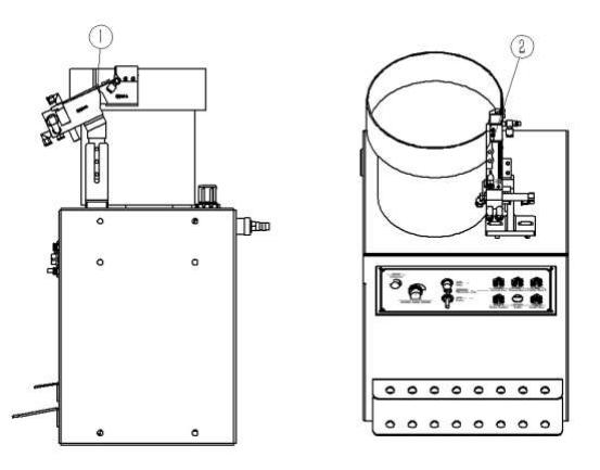
Figure 7.2
7-3-1 installation notes
1.5mm clearance between the material selection component and the selection bracket is installed on the 7-3-2 selection parts

Figure8.3 studs, screws and water - proof nut selection assembly
1.material splitting part 2.cover 3.block 4.air cylinder 5.base 6. connection plate 7.supporter

Figure 8.4 nut selection assembly
1.material splitting part 2.cover 3.block 4.air cylinder 5.base 6.connection plate 7.supporter
3-3、feeding part
1.air cylinder 2.fixing plate 3.connection plate 4.connection plate 5.connection plate 6.hinge 7.pin 8.cover

Figure 8.6 nut feeding assembly(upper feeding)
1.air cylinder 2.fixing plate 3.connection plate 4.stop part 5.ejector 6.cover 7.hinge 8.pin 9.chute plate

Figure8.7 nut feeding assembly(bottom plate feed)
1.air cylinder 2.cover 3.ejection 4.lower tool 5.stopping part
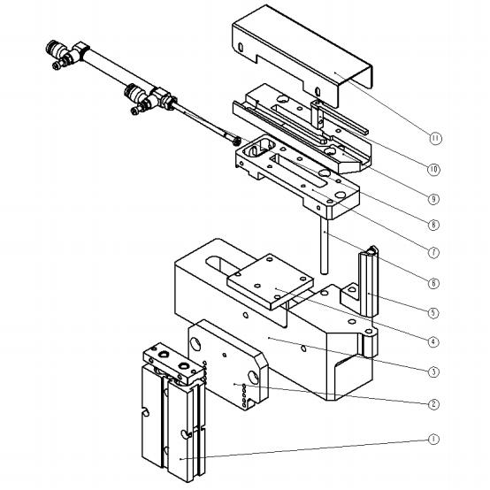
1. Lifting cylinder 2. Lifting cylinder mounting plate 3. Lower mold seat 4. Lifting plate 5. Lower mold 6. Guide rod 7. Feeding cylinder 8. Installation plate 9. Feeding cylinder 10. Material channel 11. Feeding push rod 12. Protective cover
3-4、upper tool punch
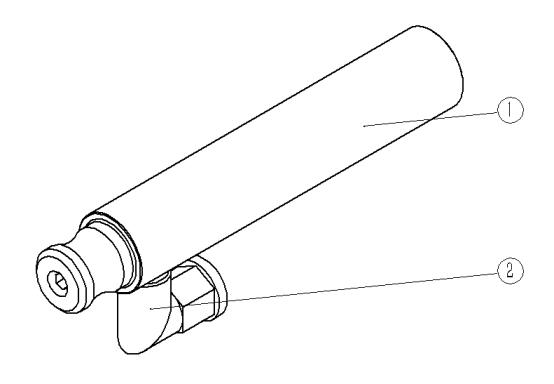
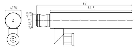
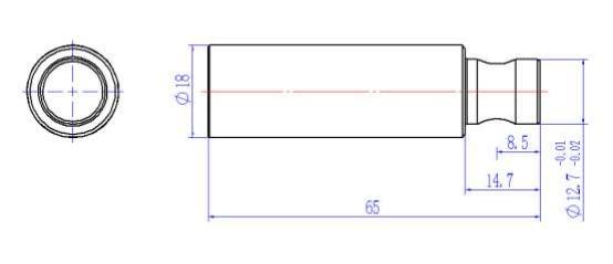
Figure 8.9 blind hole studs, screw upper tool
1.upper tool punch 2.Vacuum tube joint
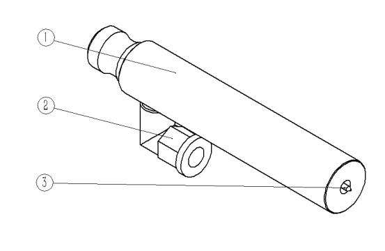
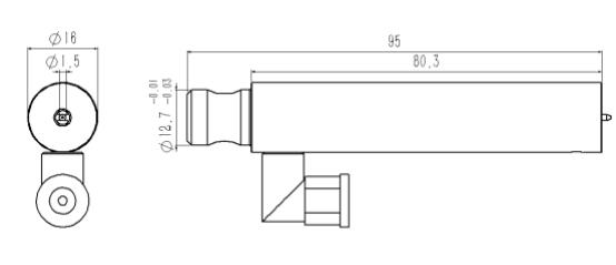
Figure 8.10 through-hole studs, screw upper tool
1.upper tool punch 2.Vacuum tube joint 3.Insert needle
3-5、lower tool holder

Figure 8.11 studs, screw lower tool
1.nut 2.spring 3.pin 4.lower tool
8、automatic tool testing
1、nut avoiding feed
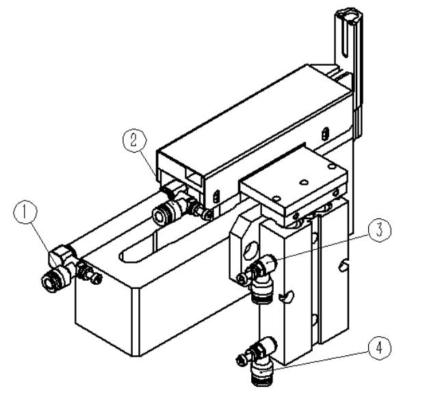
Figure 8.1
FIG. 1, 2, 3 and 4 are all throttle valves.
Throttle valve 1: Control the ejector (FIG. 8.1) return speed, clockwise rotate throttle valve, the ejector back speed is slowed down, whereas speed is accelerated.
Throttle valve 2: Control the ejector (FIG. 8.1) push speed, clockwise rotate throttle valve, the ejector push speed is slowed down, whereas speed is accelerated.
Throttle valve 3: Control the ejector (FIG. 8.1) rising speed of air cylinder 2, clockwise rotate throttle valve, the rising speed is slowed down, whereas speed is accelerated.
Throttle valve 4: Control the ejector (FIG. 8.1) falling speed of air cylinder 2, clockwise rotate throttle valve, the falling speed is slowed down, whereas speed is accelerated.
troubleshooting
A:The feeding height is not enough, the nut can not be delivered to the lower tool, and the throttle valve 3 is adjusted counterclockwise to accelerate the rising speed.
B:The feed position is not in place, then counterclockwise adjust throttle valve 2, speed up the pushing speed.
C: FIG. 8.1 when the cylinder 2 drops, the ejector is stuck on the lower tool, causing it to be unable to drop. then counterclockwise adjust throttle valve 1, speed up the ejector returning speed.
2、studs 、screw feeding
Adjust from front to back
Loosen the screw 3 ,screw 4, 5, move the feed assembly to appropriate location, the hinge (figure 8.8) hole and the upper tool is almost coaxial, adjust screw 4 again, make the hinge hole coaxial with upper tool. Lock the screw 3, screw 5, and finally tighten the screw 4.
Note: adjustment is made only when the feeding assembly is installed for the first time. The screw and screw feeding components will be replaced after, no further adjustment is required.
Adjust from left to right
Loosen the screw 8, move the feed assembly to appropriate location, finally tighten the screw 8.
Adjust up and down
Loosen the screw 6 and 7, move the feed assembly to appropriate height, finally tighten the screw 6 and 8.
Adjust feeding speed
The throttle valve 1 is adjusted clockwise to slow the feeding speed and vice versa.
If the insertion feeding is unstable, adjust the feeding speed.
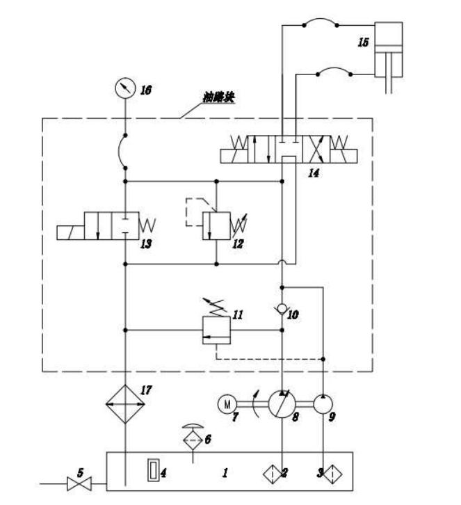
9、Hydraulics Schematic
10、Electrical System
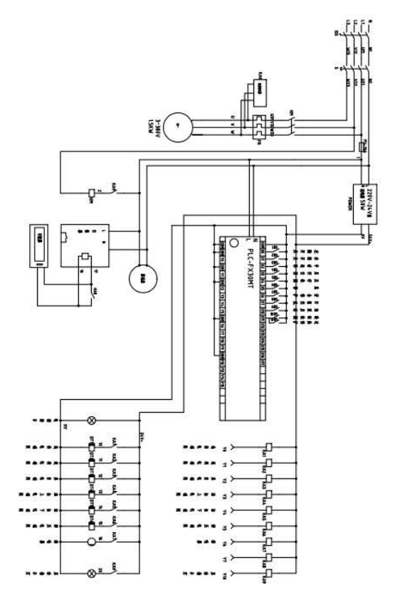
11、Machine Maintenance
oil dirt
Level: | normal |
Schedule: | Diário |
Maintenance: | The surface of the machine is clean, tidy, and free of oil stains |
Maintenance object: | 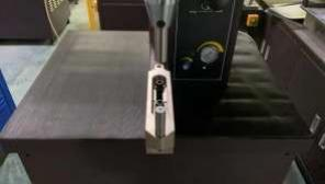 |
safety protection ram bush
Level: | Importante |
Schedule: | Diário |
Maintenance: | The ram can move back and forth smoothly, the inside wall has no dirt. |
Maintenance object: | 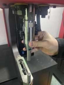 |
NC safety protection switch
Level: | Importante |
Schedule: | Diário |
Maintenance: | Test with insulating materials |
Maintenance object: | 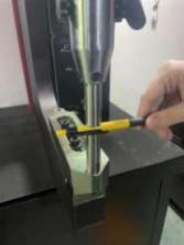 |
Automatic up and down mold
Level: | Importante |
Schedule: | Semanal |
Maintenance: | Clean the automatic upper and lower molds |
Maintenance object: | 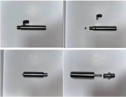 |
Vacuum filter screen
Level: | Importante |
Schedule: | Mensal |
Maintenance: | Replace the vacuum filter of the pneumatic system |
Maintenance object: | 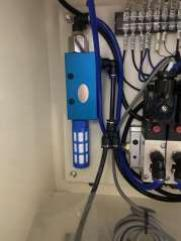 |
Auto feed system
Level: | Importante |
Schedule: | Mensal |
Maintenance: | Check if the airway, the solenoid valve, the vibration frequency is normal |
Maintenance object: | 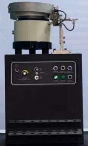 |
Sistema hidráulico
Level: | Importante |
Schedule: | Yearly |
Maintenance: | Check whether the oil circuit element is normal, the seal is normal, the oil circuit system |
Maintenance object: |  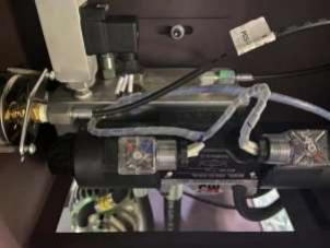 |
Pilot circuit
Level: | Importante |
Schedule: | Yearly |
Maintenance: | Check whether the circuit is normal (the professional staff with the electrician certificate) |
Maintenance object: |  |
Sistema hidráulico
Level: | Importante |
Schedule: | Yearly |
Maintenance: | Change the hydraulic oil once a year. 46 #, 32# (recommended using mobil or shell) |
Maintenance object: | 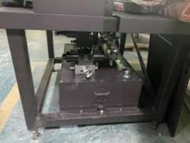 |
12、troubleshooting
Problema | Fonte | Solução |
|---|---|---|
machine will not turn on | 1. blown fuse 2. no power to machine 3. overload relay tripped 4. circuit breaker tripped | 1. replace fuse 2. check for correct power supply 3. reset overload relay 4. repair fault and reset |
machine starts but ram will not come down | 1. pump direction of rotation is reversed 2. upper tool holder is sticking 3. foot pedal works 4. Check whether the circuit board power fuse is blown | 1. Check arrow on side of motor to verify correct rotation. Reverse 2. L1 and L2 leads to change rotation 3. if needed. 4. Remove and clean upper tool 5. holder, lube with white grease. 6. Check the foot switch, wiring is fixe or foot pedal is damaged or not. |
When in the operation mode, ram will not come down | 1. non conductive material 2. The safety switch cannot be cut off. 3. ram power cable disconnect 4. Check the circuit system safety protection power output | 1. clean tool surface 2. replace safety switch 3. re-connect ram power 4. replace electrical component 5. replace electrical component |
Auto feed system can not work | 1. Whether the air tube connection position is correct. 2. Whether the tooling is inserted properly 3. dirt on the tool, then get stuck 4. pneumatic solenoid valve is damaged. 5. no air or air pressure is not enough | 1. re-connect air tube 2. re-insert tube 3. remove and clean 4. replace pneumatic solenoid valve 5. connect air, increase air pressue |
13、machine parameter

tipo | M618-NC | M1025-NC |
|---|---|---|
Força | 2~57 | 6~97 |
Throat depth(mm) | 450 | 650 |
throat height(mm) | 400 | 450 |
stroke(mm) | 200 | |
voltage(V) | 380 | |
power(KW) | 1.5 | 3.0 |
current(A) | 4 | 8 |
Estágio | 3 | |
motor frequency(Hz) | 50/60 | |
hydraulic oil | 46#/32# | |
capacity of oil tank(L) | 65 | |
air pressure(Kg) | 5~7 | |
dimension Lx W x H | 93 × 110×200 | 107×156×220 |
weight(Kg) | 650 | 1100 |
14、pressure convert table
system pressure (Mpa) | upper tool pressure (Kg) | |
|---|---|---|
M618 | M1025 | |
0.5 | 131.25 | 226.65 |
1 | 262.5 | 453.3 |
2 | 525 | 936.6 |
3 | 787.5 | 1359.9 |
4 | 1050 | 1813.2 |
5 | 1312.5 | 2266.5 |
6 | 1275 | 2719.8 |
7 | 1837.5 | 3173.1 |
8 | 2100 | 3626.4 |
9 | 2362.5 | 4079.7 |
10 | 2625 | 4533 |
11 | 2887.5 | 4986.3 |
12 | 3150 | 5439.6 |
13 | 3412.5 | 5892.9 |
14 | 3675 | 6346.2 |
15 | 3937.5 | 6799.5 |
16 | 4200 | 7252.8 |
17 | 4462.5 | 7706.1 |
18 | 4725 | 8159.4 |
19 | 4997.5 | 8612.7 |
20 | 5230 | 9066 |
21 | 5512.5 | 9519.3 |
22 | 5775 | 9972.6 |
1Mpa=10Kg/cm2 1KN=100Kg